
Application showcase
Integration of an attocube ANRv51 Rotator into a kiutra L-Type Rapid cryostat for sub-Kelvin angle-resolved measurements
We report on the integration of an attocube ANRv51 rotator into an L-Type Rapid cryostat, enabling precise angle-resolved measurements at millikelvin temperatures. We evaluate the thermal performance of the experimental setup, establish suitable operating parameters, and outline limitations and best practices for reliable operation.
Collaborative partners: attocube systems GmbH; kiutra GmbH.
Products: kiutra L-Type Rapid cryostat, attocube ANRv51/RES+ rotator + AMC300 controller.
Introduction
Angle-resolved measurements are vital for studying anisotropic electronic, magnetic, and superconducting properties of quantum materials, yet conventional setups are slow and complex. The integration of an attocube ANRv51 rotator in a kiutra L-Type Rapid (LTR) cryostat offers a straight-forward and fast solution for angle-resolved studies at millikelvin temperatures. This note investigates the performance of the rotator in the LTR and outlines guidelines for a successful operation at temperatures down to 100 mK.
Experimental setup
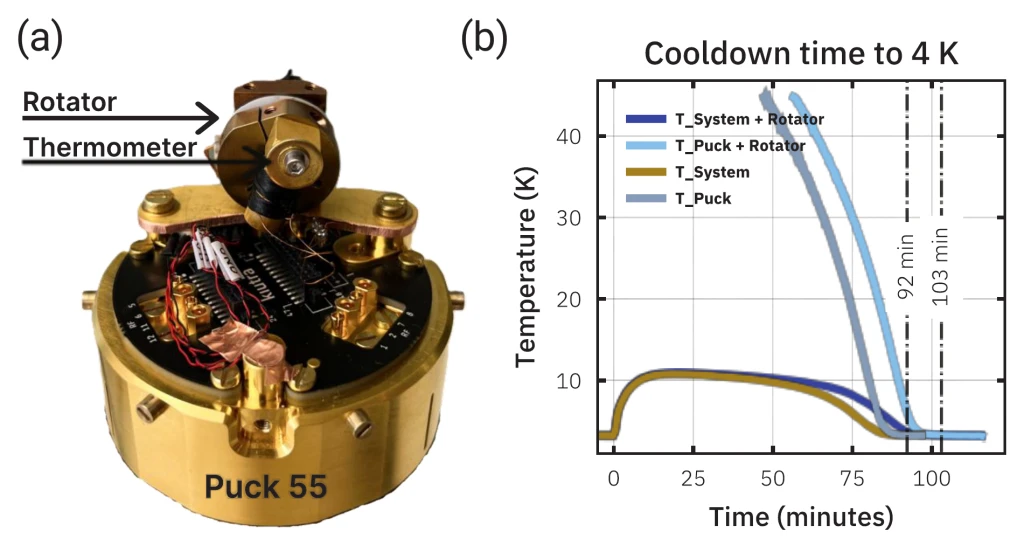
The ANRv51 rotator was mounted on a kiutra LTR Puck 55 with a dedicated thermometer mounted either on the puck or directly on the rotator’s experiment platform, to monitor the Puck and rotator temperature during operation (c.f. Figure 1-a). The rotator was connected to the Cryostat’s DC wiring providing a line resistance of < 2.5 Ohms per line to comply with rotator operation requirements. The rotator is operated using the attocube AMC300 controller. In the following we will present the cooldown performance of the assembly, the impact on cooling performance during rotator operation, and derive best practices for the operation of an ANRv51 rotator in the LTR.
Cooldown performance
Initially, the cooldown behavior from room temperature was investigated. Therefore, one sample loading was performed both with an empty Puck, as well as with a Puck with rotator assembly. We find that the integration of the rotator adds around 10 minutes to the bare system cooldown time to 4 K (see Figure 1-b).
Following stabilization at 4 K, the system is cooled down further to 100 mK, where the rotator requires an additional thermalization time of around 5-10 minutes to be in thermal equilibrium. We record a temperature offset of around 20-30 mK between sample puck and rotator platform at 100 mK cryostat temperature. The remaining temperature difference between rotator platform and sample puck needs to be accounted for in a measurement, and the use of a dedicated sample thermometer is recommended.
Low temperature operation
Next, the heating effects resulting from rotator operation at millikelvin temperature are investigated. Therefore, the cryostat’s sample stage was thermally isolated from the main thermal bath and the system’s temperature response during rotator operation is observed. Activating the axis and resistive position readout does not affect the sample stage temperature, given a sensor power below −10 dB is used.
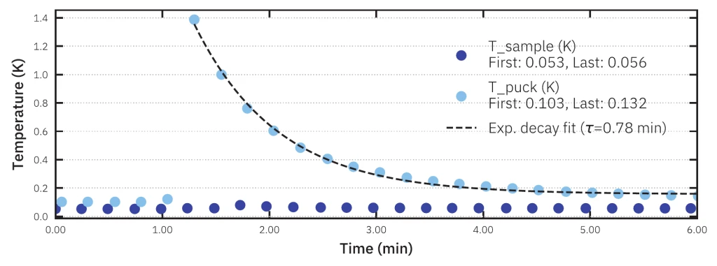
To characterize the thermal behavior during rotation, movements of 100 steps at a time were performed using 250 Hz and 60 V pulses with a sensor power of -10dB for readout. Each movement generated a local heat pulse. To estimate heat deposition per movement, the time required for the sample stage to return to equilibrium was recorded (cf. Figure 2). Depending on the operation temperature, equilibrium was reached after 0.3 to 1 minute. The increased equilibrium temperature after each heat pulse provides a direct measure of the total energy deposited during rotator motion.
Larger angle rotations were performed, allowing sufficient relaxation time after each 100-step movement to prevent line overheating. In this mode, a full 180° rotation can be performed within around 30 minutes, without system overheating.
Best practices
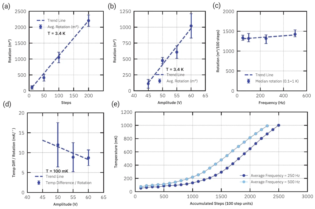
This section investigates the impact of key drive parameters on rotator performance at cryogenic temperatures and derives best practices for the use of the rotator in an LTR. To evaluate the dependence on the drive amplitude, the rotator was operated in 100 step sequences at 45 V, 50 V, 55 V, and 60 V. Figure 3b) shows a linear increase of the achieved rotation as a function of amplitude. Figure 3d) shows the mean temperature increase per degree rotation of the isolated sample stage. We find that amplitudes between 55 V and 60 V show the best operating conditions and all further tests are conducted using a 60 V excitation.
Similarly, the rotation over 100 steps increments was evaluated for drive frequencies from 50 Hz to 1000 Hz. All frequencies above 50 Hz show an average rotation of ~1350 m° per 100 steps as shown in figure 3c). To examine thermal effects of different drive frequencies, the sample stage was cooled down to 100 mK and decoupled from its environment. Subsequently the rotator was operated in 100 step increments at 250 Hz and the same operation was repeated at 500 Hz. Figure 3e) shows that in both operation scenarios, the sample stage temperature slowly increases due to rotator motion, however, we see a significantly higher heat-load when operating at 500 Hz. Hence, the results indicate frequencies below 250 Hz as the optimal frequency for low temperature operation.
Using those parameters, the relation between steps and angular movement was determined by performing movements between 10 and 10 000 steps and recording the rotators position. Figure 3a) shows that we observe largely linear behavior over the full range of parameters. Thus, larger angular rotations can be achieved by performing more steps at a time. However, the maximum number of steps before waiting/cooldown period is limited by local heating which leads to overheating of the superconducting DC lines. Larger rotations should therefore be performed in consecutive movements of 100-200 steps with waiting times of 1-5 minutes between the steps. Table 1 summarizes the evaluated parameter range and the recommended settings for the operation in an LTR at millikelvin temperatures.
| Parameter | Parameter range | Best |
|---|---|---|
| Amplitude | 45–60 V | 60 V |
| Frequency* | 1–1000 Hz | 250 Hz |
| Step Count* | 1–10 000 | 100 |
| Sensor Power | 0 to −20 dB | -15 dB |
Taken together, the full cooldown time of the rotator assembly to 100 mK remains less than 4 hours, enabling very fast access to angle-resolved studies at millikelvin temperatures.
Conclusion
Integrating the attocube ANRv51 into a kiutra L-Type Rapid cryostat enables reliable, fast, and precise angular measurements down to 100 mK. We have shown that integrating a rotator on the sample puck does not significantly impact the fast-turnaround cycles achieved by the L-Type Rapid and we derived suitable operation parameters for the rotator at millikelvin temperatures. This enables for the first time the fast characterization of anisotropic quantum materials and magnetic systems at large magnetic fields and millikelvin temperatures.
About attocube
attocube is a leading nanotechnology company based in Munich, Germany. We aim to enable cutting-edge research by delivering precision motion and sensing solutions for extreme environments. Our portfolio includes cryo-compatible nano positioners, scanners, and interferometric sensors and microscopy solutions that operate reliably at ultra-low temperatures, in high magnetic fields, and under vacuum conditions.
Take this information with you.
Download PDF
Contact
Get in touch with our team
From first experiments to scaled-up quantum systems, our team can help you find the right cooling system for your work.