CRYOGENIC SERVICES / RF TRANSMISSION
RF Transmission measurement as a service
CRYOGENIC SERVICES / RF TRANSMISSION
RF Transmission measurement as a service
Transmission measurements at cryogenic temperatures are essential for characterizing RF components such as cables, attenuators or filters. They provide insight into key parameters like the signal strength, phase response, and temperature-dependent behavior. By using a vector network analyzer (VNA), scattering-parameters are measured to determine the transmission and reflection characteristics of RF components over a defined frequency range.
Click image to enlarge
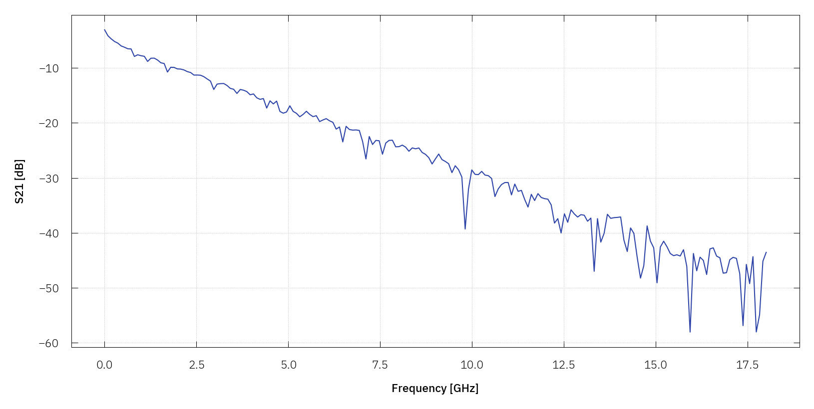
Forward transmission S21 of an unattenuated line as a function of frequency.
How does a standard RF transmission measurement work?
To analyse how RF signals behave in a Device Under Test (DUT), we use a VNA. It characterizes the electrical properties of RF and microwave components by measuring how they reflect and transmit signals. The VNA generates RF signals across a frequency range from kHz to GHz. Internally, this signal is split: one portion is sent to a reference receiver, providing a known amplitude and phase baseline, while the other is delivered to the DUT. Depending on its properties, the DUT reflects and transmits parts of the signal.
By comparing the DUT response to the reference, the VNA calculates scattering parameters (S-parameters). In a two-port setup, the key parameters are:
- S11: Reflection at port 1 (input)
- S22: Reflection at port 2 (output)
- S21: Forward transmission from port 1 to port 2 (gain or loss)
- S12: Reverse transmission from port 2 to port 1
For a standard RF Transmission measurement, it is sufficient to focus on S21. For this, the sample is cooled to the lowest target temperature, and a frequency sweep is performed while recording S21. Additionally, the frequency sweep can be repeated at different RF powers and/or at defined temperature steps to investigate power and temperature dependencies.
The input RF line (from the VNA port, through the entire cryostat wiring to the sample input port) is calibrated, accounting for all components in the signal path, including cables, attenuators, and connectors. Knowing the total attenuation enables accurate calculation of the actual power delivered to the resonator port, which is essential for determining the average photon number during measurements.
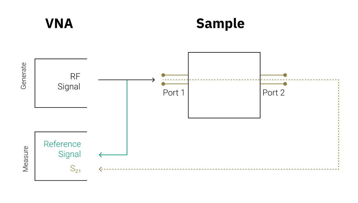
Schematic of the measurement setup. The Vector Network Analyzer includes an RF source and receiver, enabling generation of an RF signal and measurement of the transmission (S21) from port 1 to port 2 by comparing it to a reference signal.
Sample carrier and breakout
Depending on the geometry and connector type of the sample, kiutra evaluates the availability of suitable sample holders or supports the design of custom sample holders where necessary.
Once prepared, the DUT, which can either be mounted onto a sample holder or connected directly, is connected to a kiutra puck. When the puck is loaded into a kiutra L-Type Rapid cryostat, its RF connectors automatically mate with the cryostat’s internal RF wiring. The VNA is connected to the corresponding input and output cryostat RF lines.
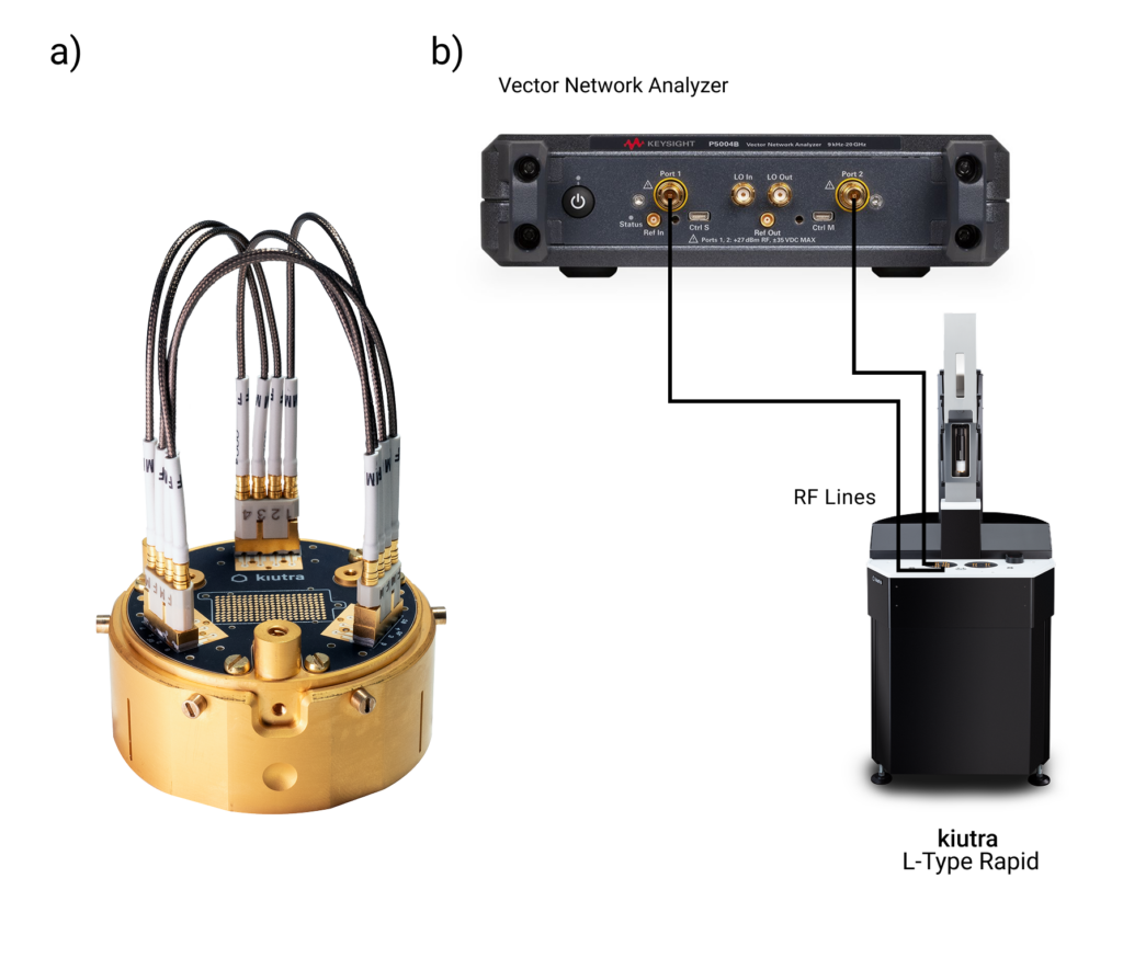
a) Example setup of six RF cables directly connected to a kiutra Puck 55. No additional sample holder is required in this configuration.
b) Room temperature measurement setup consisting of a Keysight P5024B Vector Network Analyzer, additional amplifier and/or attenuators and a kiutra L-Type Rapid cryostat.
Standard measurement protocol
1. The kiutra puck with the DUT is loaded into the cryostat and cooled down to bath temperature (3 – 4 K).
2. The puck is further cooled down to the target temperature.
3. At the stabilized temperature setpoint, a frequency sweep is performed while recording the transmission using a vector network analyzer.
4. Optional: The frequency sweep is repeated at different RF power steps.
5. Optional: The frequency sweep is repeated at different temperature steps.
6. The puck is removed from the cryostat and warmed up to room temperature.
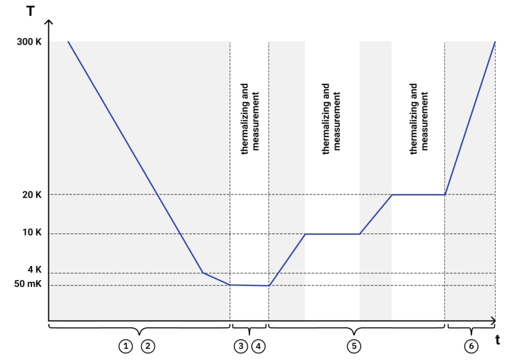
Example measurement: temperature dependency of a frequency sweep. The temperature curve shows the initial cooldown, waiting periods for thermalization, discrete temperature steps at 50 mK, 10 K, and 20 K (example setpoints) during which the measurement data are recorded, and the final removal of the puck.
Parameters:
* The power range can be adjusted by using different input line configurations.
** Value has to be provided by the customer prior to the measurement and must be within the specified range.
The following input line configurations can be chosen:
Can’t find what you need?
We support custom measurement requests for setups outside our standard protocol. Please get in touch for a quote. This will include a one-time setup fee. If you run the same measurement again later, we will reuse the protocol at no extra cost.
Email us at: info@kiutra.com.