
Back to Measurement as a Service
Services
IV Measurements
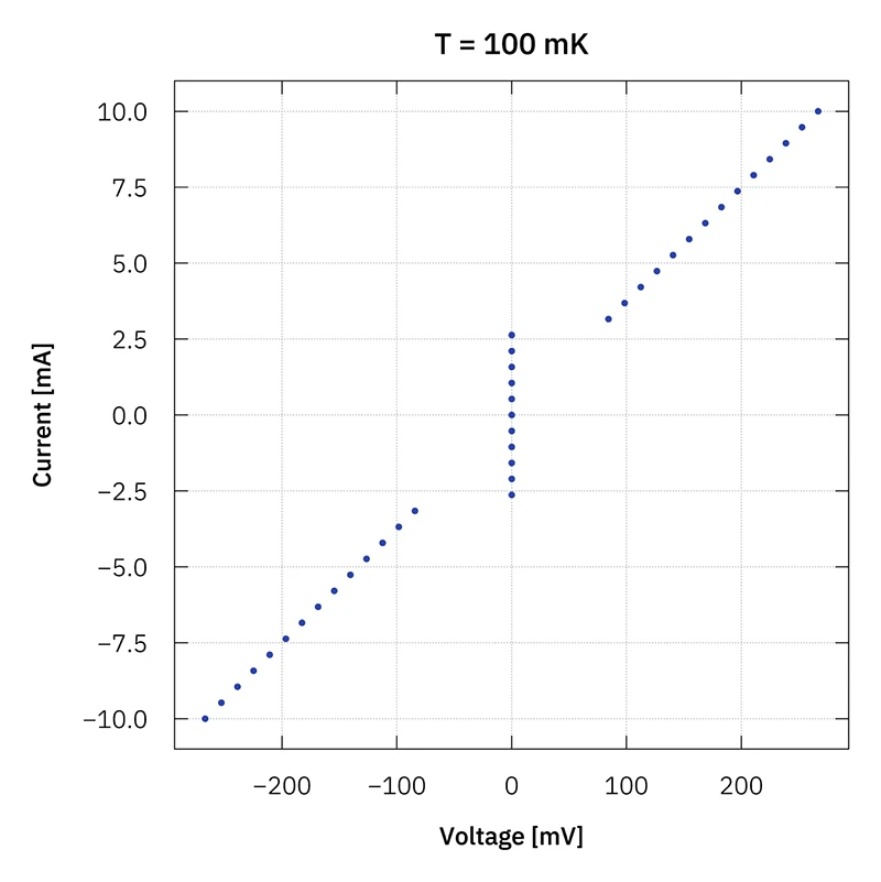
Current–voltage (IV) measurements at cryogenic temperatures are a key technique for studying the transport properties of semiconducting devices, such as field-effect transistors (FETs), diodes, and nanostructures. IV characteristics describe how much electrical current flows through a device when a certain voltage is applied – or, conversely, which voltage develops when a defined current is driven through the device. They reveal key properties like the voltage at which a device turns on, the resistance of electrical contacts, and non-linear current behavior. These properties strongly depend on temperature and the quality of the material.
How does a standard IV measurement work?
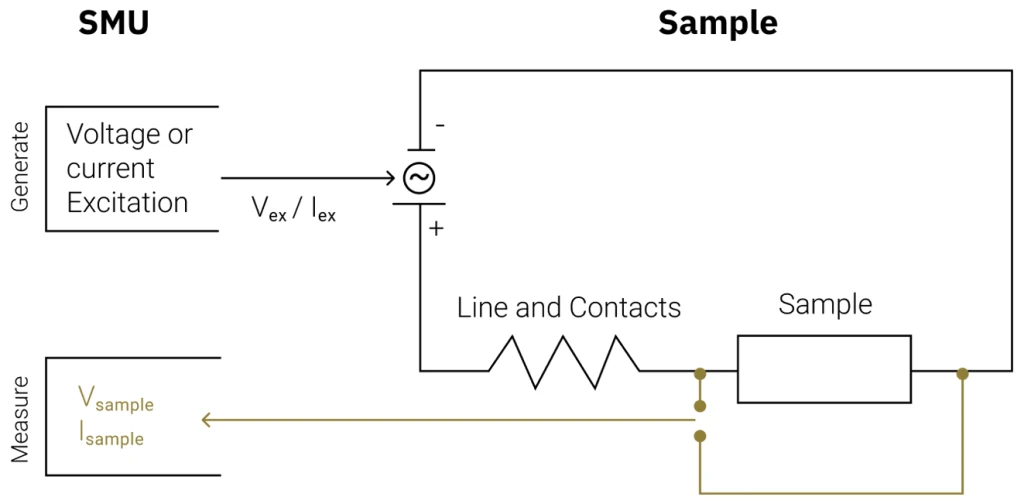
A standard IV measurement is performed at a fixed temperature by exciting the device with either a voltage or a current and simultaneously measuring both the resulting voltage and current. Our measurement setup employs a precision source-measure unit (SMU) that performs sourcing and measuring within a single instrument.
The SMU can operate in two complementary modes, which determine how the experiment is controlled. In voltage-source mode, a defined voltage is applied to the device, and the resulting current is measured. In current-source mode, it is the other way around. The choice between voltage-source and current-source mode is mainly determined by the response of the device under test. In general, the parameter that causes a steep or abrupt response should be controlled, while the resulting quantity is measured.
Two-point measurement
In a two-point measurement, the same pair of electrical leads is used to measure the response. Thus, the measured result includes contributions both from leads and contacts, as well as from the sample. This method only requires two contacts on a sample. It is less accurate than a four-point measurement and is usually used only when contact and lead resistances are negligible compared to the device resistance.
Four-point measurement
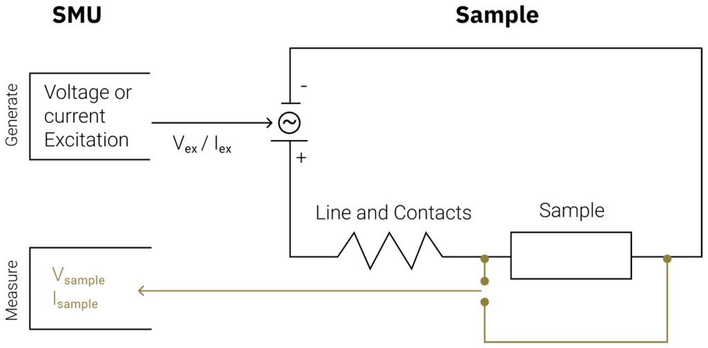
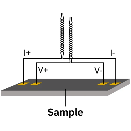
In contrast, in a four-point measurement, the response is measured using two separate voltage leads connected close to or directly to the sample. This eliminates any contribution from wires or contacts, ensuring that the measured result reflects only the sample itself.
When a device is biased continuously (applying a constant electrical voltage or current), electrical power is dissipated as heat. At ultra-low temperatures, this may lead to sample self-heating and thereby distort the intrinsic transport characteristics. The measurement is therefore performed in pulsed operation, ensuring thermal relaxation time for the device and surrounding cryogenic environment. This approach minimizes Joule heating effects while still enabling the reliable extraction of IV characteristics over a wide dynamic range.
Additional control voltages
In addition to the voltage or current excitation, some devices, such as field-effect transistors (FETs), require additional voltages like a gate voltage. To ensure independent control and a clear separation, this is applied via a separate dedicated power supply.
Sample carrier and breakout
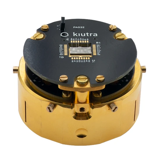
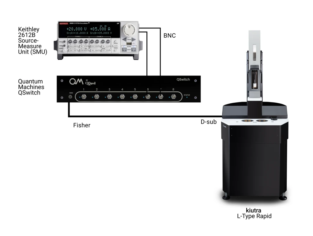
kiutra offers sample carriers for mounting and electrically contacting devices. After the measurement, the sample carrier is returned to the customer for further use. All our sample carrier pads provide a 10 × 10 mm cutout for mounting devices, which can be attached to a gold-plated, high-purity oxygen-free copper (OFHC) plate. If multiple samples are placed on the sample carrier, the parameters are recorded by using two SMU channels (with four terminals each) and two QSwitch switching matrixes. Alternatively, we can evaluate the compatibility of customer-provided sample holders or support the design of custom holders for specific applications.
kiutra PAD32
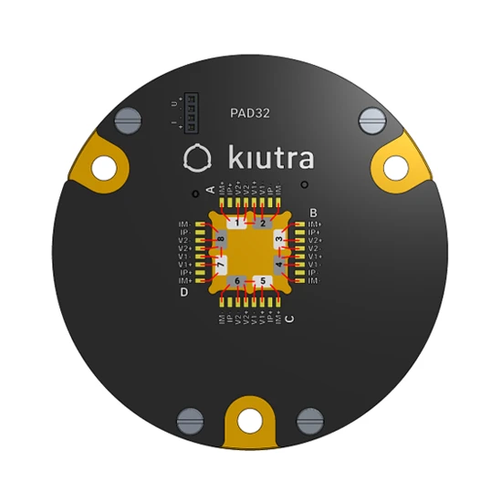
The PAD32 features 32 gold-plated bonding pads and offers space for up to eight samples. The pad layout is specifically optimized for four-point measurements by assigning dedicated twisted pairs for excitation and sensing. This design streamlines wire bonding, minimizes bond lengths, and avoids wire crossings.
kiutra PAD48
The PAD48 features 48 gold-plated bonding pads and offers space for up to twelve samples. In contrast to the PAD32, the PAD48 uses a conventional pad assignment (e.g. A1/A2, B1/B2), offering maximum flexibility. While four-point measurements are equally supported, wire bonding may involve longer bonds and crossings depending on the device layout.
Cryostat interface
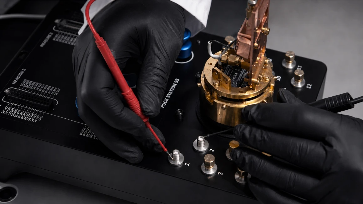
The prepared sample carrier is mounted onto a puck and seamlessly connects with the on-puck DC connectors. When loading the puck into an L-Type Rapid cryostat, the DC lines from the puck automatically mate with the internal twisted-pair wiring. At the top plate, the DC lines are divided into two D-Sub 25 connectors. They are connected via two 24-pin, twisted-pair, double-shielded measurement cables to a dedicated transport breakout box.
Standard measurement protocol
The kiutra sample puck with the sample carrier and the mounted, wire-bonded device is loaded into the cryostat and cooled down to bath temperature (~ 3K).
The puck is further cooled down to the lowest target temperature (50 mK or 100 mK).
An excitation sweep (voltage or current) is performed while both the voltage and current response of the device are measured using the SMU.
The temperature is set to the next target temperature, stabilized, and step three is repeated.
Once the measurement is concluded, the sample puck is unloaded from the cryostat.
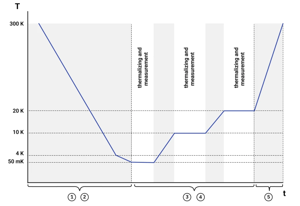
Parameters:
| Parameter | Value |
|---|---|
| Excitation current* | 1 nA – 100 mA |
| Excitation voltage* | 10 µV – 10 V |
| Power limit** | 15 µW at 300 mK 25 µW at 500 mK 80 µW at 1 K |
| Temperature range* | 0.05 K – 40 K 0.1 K – 300 K |
* Setpoints have to be provided by the customer prior to the measurement and must be within the specified range. ** If the specified limit is reached, the measurement is automatically stopped to prevent heating and long thermal recovery times.
Configure your IV measurement
Temperature steps for determining an I–V curve, with optional bias / gate voltages and room-temperature measurements. Instruments: source-measure unit, additional power supply (e.g., QDAC), Qswitches.
Contact
Talk to our team
Have a question about this measurement, need help with the configurator, or looking for something outside our standard protocol? Get in touch. Custom requests include a one-time setup fee, and if you run the same measurement again later, we’ll reuse the protocol at no extra cost.