
Back to Measurement as a Service
Services
Thermometer Calibration
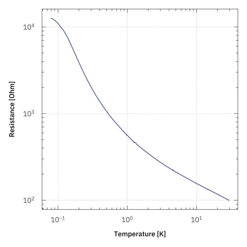
Accurate temperature measurement is essential for low-temperature experiments and therefore requires well-calibrated sensors. The relationship between a sensor's electrical response and the actual temperature is measured using a certified reference thermometer. The resulting calibration curve allows precise conversion of the sensor signal into temperature.
How does a standard calibration measurement work?
To obtain an R–T calibration curve, the sample is cooled to the lowest target temperature, followed by discrete temperature steps. At each temperature setpoint, a waiting time is applied to ensure proper thermalization before the electrical response of the sensor is recorded. The measurement is performed using an AC lock-in technique. The lock-in amplifier enables precise readout even at very low signal levels by referencing all measured signals to a fixed excitation frequency. This ensures that only voltage responses at the excitation frequency contribute to the measurement, significantly improving the signal-to-noise ratio.
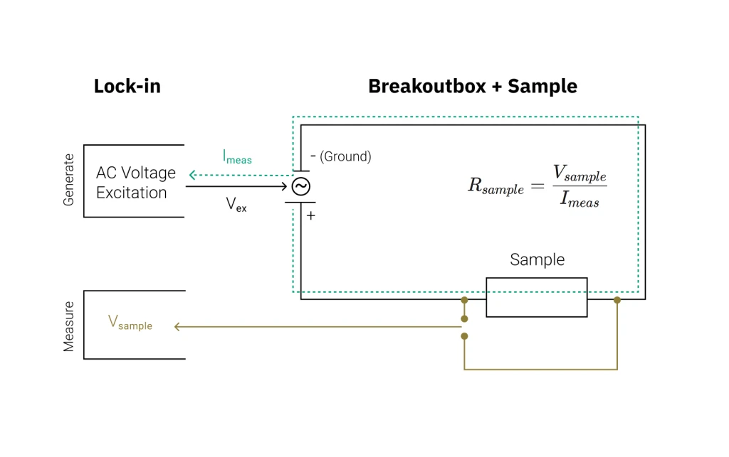
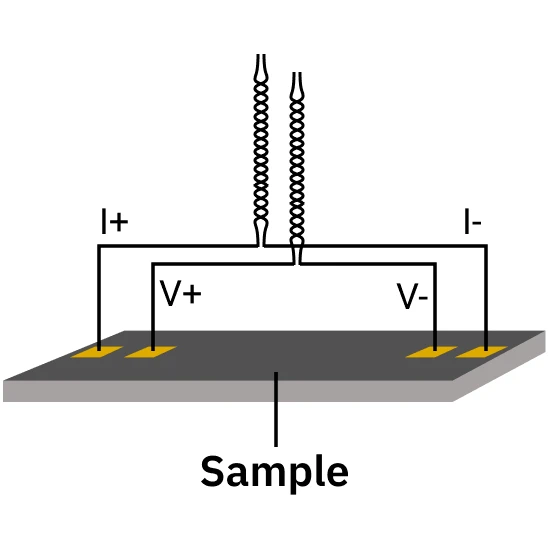
The sample is excited with a voltage provided by the lock-in amplifier. By measuring both the return current and the voltage drop across the sample, the resistance can be determined. The voltage drop is measured using two separate voltage leads which are connected close to, or directly to the sample. This eliminates any contribution from wires or contact resistances, ensuring that the measured voltage reflects only the sample itself. For multiple measurement channels, the excitation can be configured individually for each measurement channel. The return current is measured for all channels individually.
Sample carrier and breakout
Kiutra offers a range of sample carriers for mounting and contacting samples. Alternatively, kiutra can evaluate the compatibility of customer-provided sample holders or support in designing custom holders for specific applications.
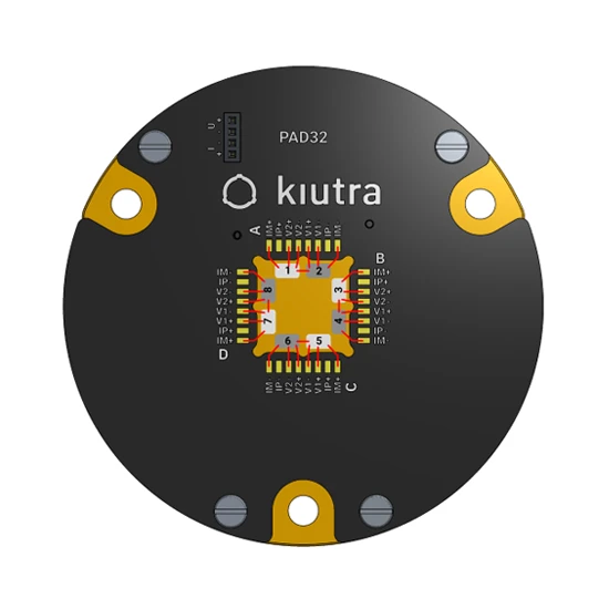
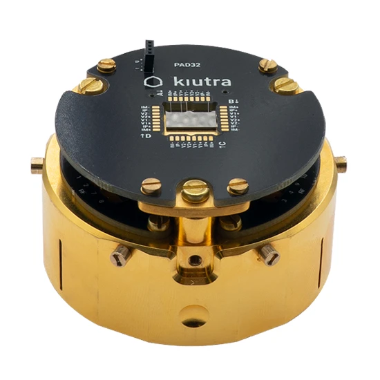
kiutra PAD32
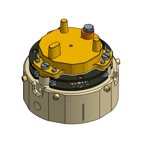
The PAD32 is a standard kiutra sample carrier that features 32 gold-plated bonding pads, optimized for four-point electrical measurements. A 10 x 10 mm cutout offers space for up to eight devices, which can be attached to a gold-plated, high-purity oxygen-free copper (OFHC) plate. After the measurement, the PAD32 is returned to the customer for further use.
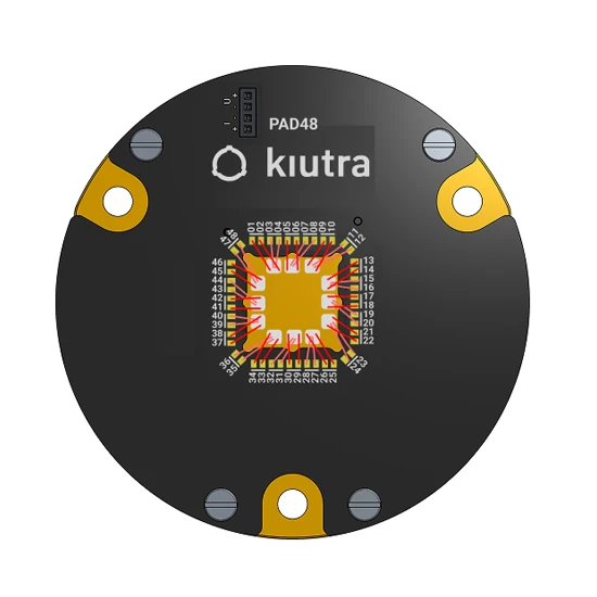
kiutra PAD48
The PAD48 is a standard kiutra sample carrier that features 48 gold-plated bonding pads. In contrast to the PAD32, the PAD48 uses a conventional pad assignment with twisted pairs side by side. This offers more flexibility, but bonds might be crossed. While four-point measurements are equally supported, wire bonding may involve longer bonds and crossings depending on the device layout. A 10 x 10 mm cutout offers space for up to twelve devices, which can be attached to a gold-plated, high-purity oxygen-free copper (OFHC) plate. After the measurement, the PAD48 is returned to the customer for further use.
kiutra Needle Card
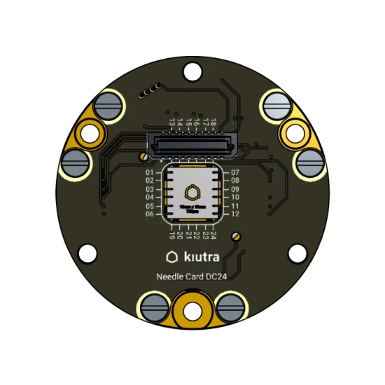
As an alternative to wire bonding, kiutra provides a needle card (probe card) solution for contacting samples, enabling non-destructive testing. The sample must be fabricated in a way that its contact pads align precisely with predefined XY positions of the probe card. kiutra offers a small range of probe card layouts for this purpose. Alternatively, kiutra offers to build custom probe cards for customer specific layouts. Electrical connections are established via Tungsten-Rhenium needles with flat 60µm tips which press against the sample pads, enabling a stable connection without bonding.
Cryostat interface
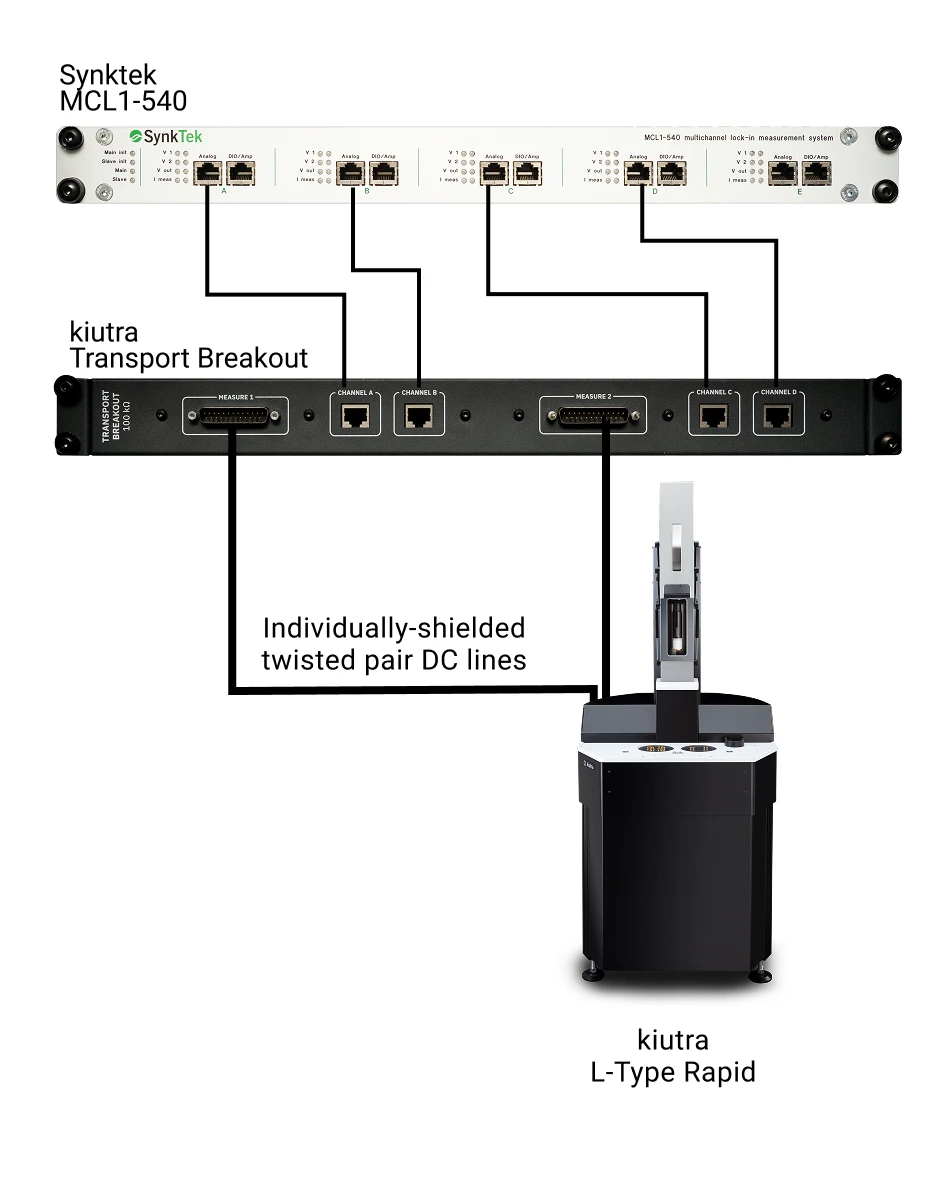
Once prepared, the sample carrier is mounted onto a puck, which seamlessly connects with the on-puck DC connectors. When loading the puck into an L-Type Rapid cryostat, the DC lines from the puck automatically mate with the internal twisted-pair DC wiring of the cryostat. At the top plate, the DC lines are divided into two D-Sub 25 connectors. They are connected via two 24-pin, twisted-pair, double-shielded measurement cables to a dedicated kiutra Transport Breakout Box, which allows mapping the lock-in channels to the cryostat's internal wiring.
Standard measurement protocol
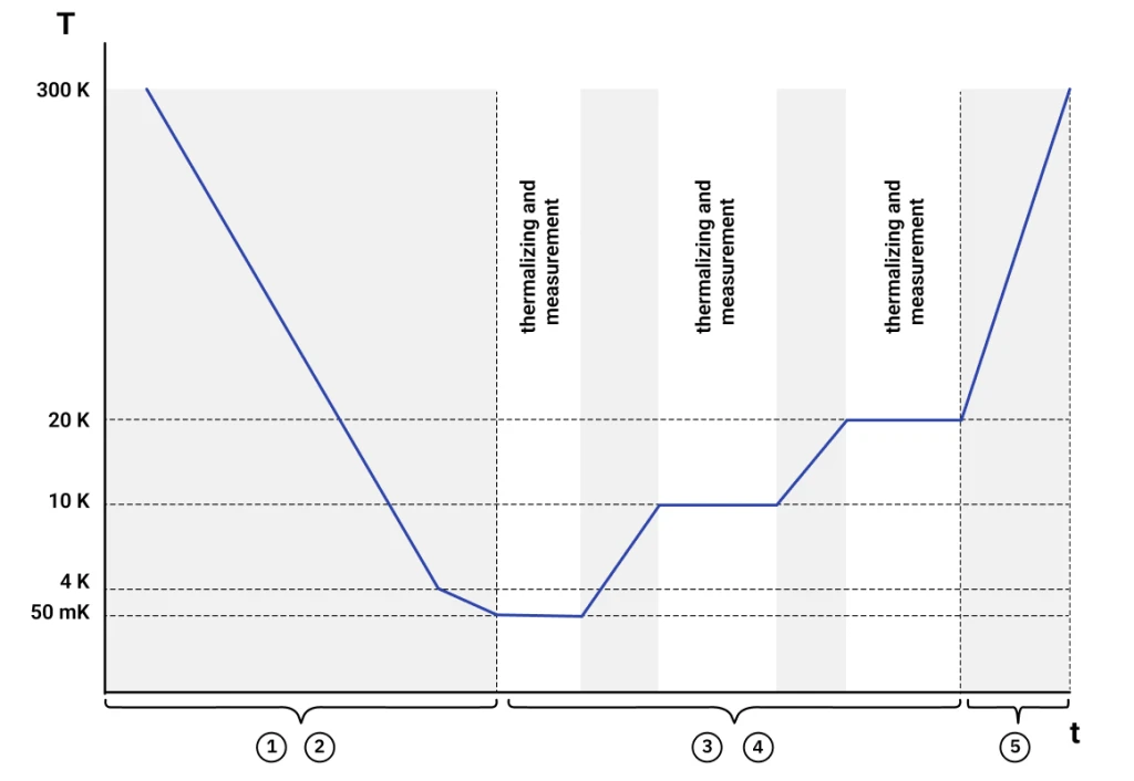
The kiutra sample puck with the sample carrier and the mounted, wire-bonded device is loaded into the cryostat and cooled down to bath temperature (~ 3K).
The puck is further cooled down to the lowest target temperature (50 mK or 100 mK) and stabilized.
At the stabilized temperature setpoint, the electrical response of the device is measured using a lock-in amplifier. The excitation and the resulting voltage response are recorded continuously. If multiple samples are placed on the sample carrier, the parameters are recorded simultaneously using multiple channels of the lock-in amplifier.
The temperature is set to the next target temperature, stabilized, and step 3 is repeated.
Once the measurement is concluded, the sample puck is unloaded from the cryostat.
Parameters:
| Parameter | Value |
|---|---|
| Excitation voltage | 1 µV – 10 V * |
| Reference frequency | 0 – 1 kHz * |
| Accessible resistance range | 20 Ω – 100 MΩ |
| Temperature range for steps | 0.05 K – 40 K* 0.1 K – 300 K* |
* Value has to be provided by the customer prior to the measurement and must be within the specified range.
Configure your thermometer calibration
Temperature steps for determining an R–T curve, with optional room-temperature measurement. Instruments: Synktek lock-in amplifier, kiutra transport breakout box.
Contact
Talk to our team
Have a question about this measurement, need help with the configurator, or looking for something outside our standard protocol? Get in touch. Custom requests include a one-time setup fee, and if you run the same measurement again later, we’ll reuse the protocol at no extra cost.