SOLUTIONS / CRYOGENICS AS A SERVICE / RESISTANCE MEASUREMENT
Resistance measurement as a service
SOLUTIONS / CRYOGENICS AS A SERVICE / RESISTANCE MEASUREMENT
Resistance measurement as a service
Resistivity or high-accuracy voltage measurements at cryogenic temperatures are essential for characterizing a wide range of materials and devices, particularly superconducting thin films.
Our state-of-the-art measurement setup employs a lock-in technique in a four-point configuration to determine a sample’s resistance as a function of temperature.
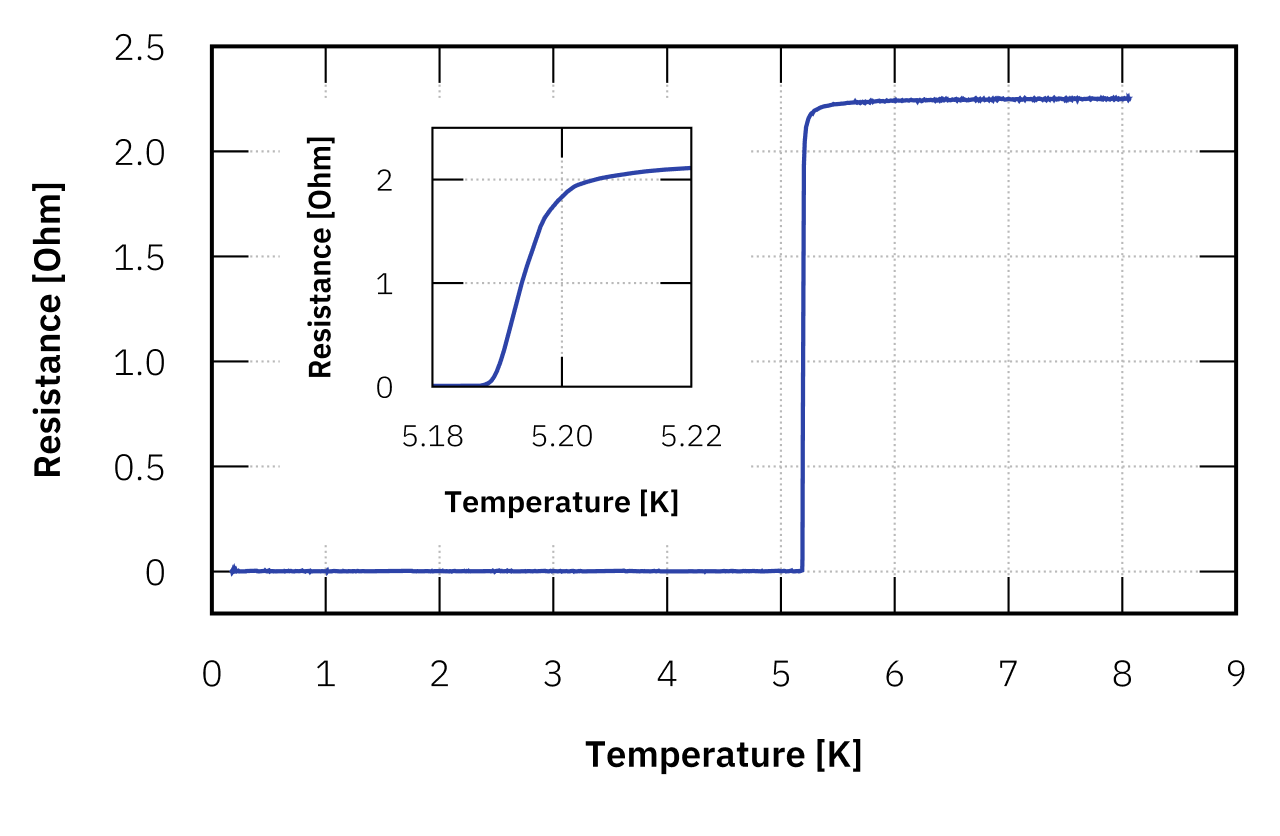
This method enables precise determination of electrical properties, such as residual resistivity and the superconducting transition temperature (Tc).
Click image to enlarge.
Example plot of the resistance as a function of the temperature for a thin-film device, where Tc was determined to be at 5.2 K. The measurement was performed within a collaboration with Zurich Instruments MFLI.
How does a standard measurement work?
To obtain an R–T curve, the sample is cooled to the lowest temperature setpoint, followed by a temperature sweep up to the highest setpoint. To determine the resistance of a sample, we use an AC lock-in technique. The lock-in amplifier allows precise resistance measurements even at very low signal levels, by referencing all signals to a fixed excitation frequency. This ensures that only voltage responses at the excitation frequency contribute to the measurement, improving the signal-to-noise ratio.
For each measurement, we will suggest an appropriate excitation current and frequency based on the estimated resistance value and application. The current is generated using the voltage excitation provided by the lock-in amplifier and a dedicated bias resistor. For multiple measurement channels, the excitation can be configured individually for each channel. As both the bias resistor and the sample are connected in series, the measurement current can vary depending on the sample resistance. Therefore, the return current is measured for all channels individually, ensuring a correct resistance value that accounts for the sample’s resistance.
The resistance of the sample can be determined using either a two-point or a four-point measurement. Our standard setup employs the four-point method, as it provides more accurate results by eliminating the influence of lead and contact resistances. The differences in setup and evaluation between the two methods are outlined below.
2-point measurement
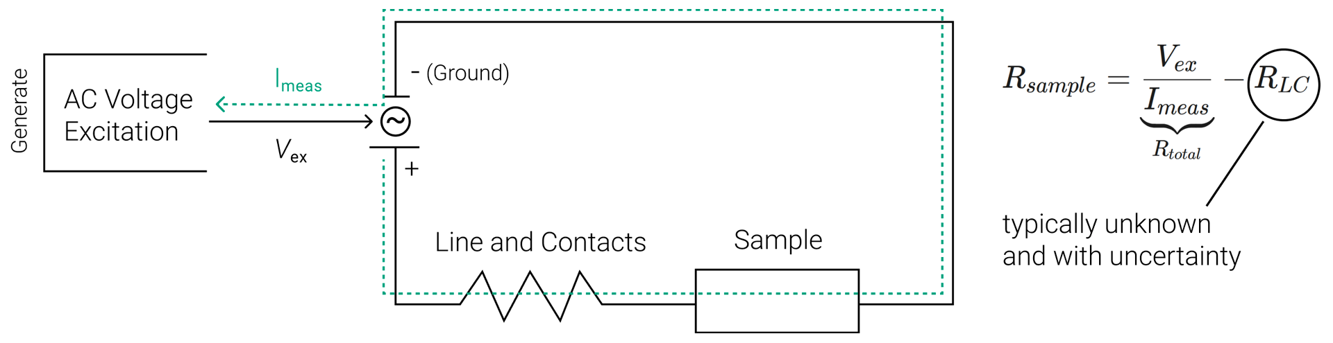
In a standard two-point measurement, a voltage is applied to a sample, and the current flow is measured using the same lines and device, typically a source measure unit (SMU). The resulting resistance therefore includes contributions both from leads and contacts, as well as from the sample. This method only requires two contacts on a sample but is less accurate than a four-point measurement, especially for low-resistance samples. This type of measurement is typically used for simple devices such as transistors or diodes, where the general characteristics of a device are investigated, rather than the specific resistance.
Click image to enlarge.
Schematic of a 2-point measurement set-up. Voltage and current are applied and measured through the same pair of contacts. The measured resistance includes the sample as well as lead and contact resistances.
4-point measurement
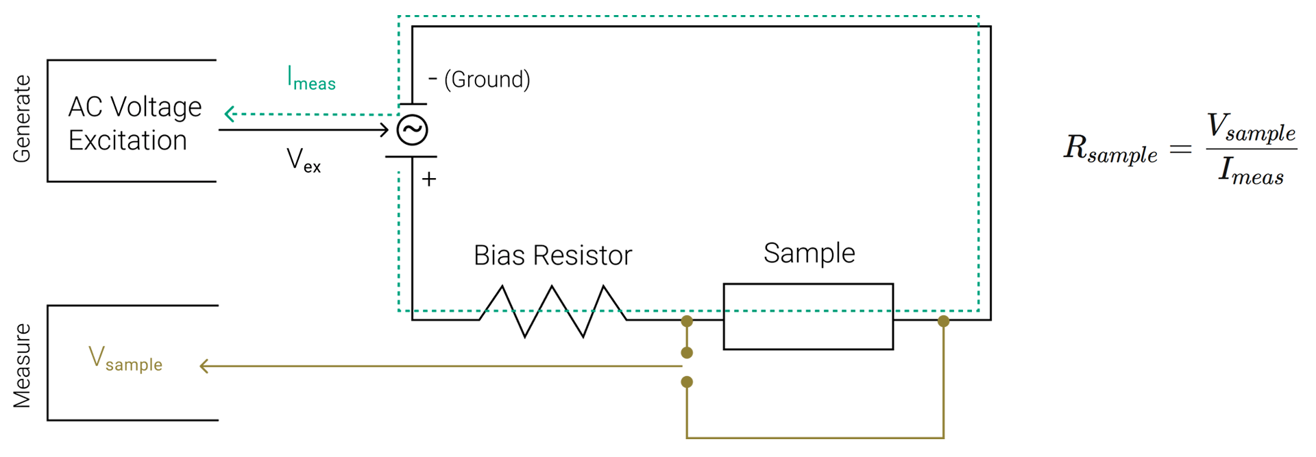
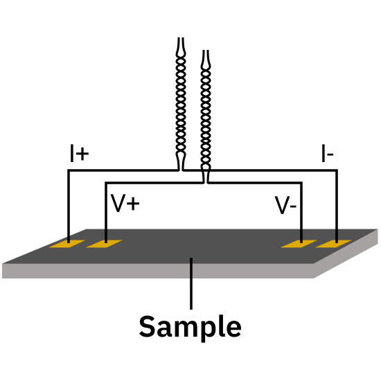
In contrast, in a four-point measurement, the voltage drop across the sample is measured using two separate voltage leads connected close to or directly to the sample. This eliminates any contribution from wires or contact resistances, ensuring that the measured voltage reflects only the sample itself. By measuring both the return current and the voltage drop across the sample, the resistance can then be determined much more accurately than in a two-point setup.
Click image to enlarge.
Schematic of a 4-point-measuement set-up. The voltage drop across the sample is measured using two separate voltage leads. This configuration eliminates lead and contact resistances from the measured voltage, allowing accurate determination of the sample resistance.
Sample carrier and breakout
We offer a range of sample carriers for mounting and contacting samples. Alternatively, we can evaluate the compatibility of customer-provided sample holders or support you in designing custom holders for specific applications.
PAD 32
PAD32 is a standard sample carrier featuring 32 gold-plated bonding pads, optimized for four-point electrical measurements. A 10 x 10 mm cutout offers space for up to eight devices that can be attached to a gold-plated, high-purity oxygen-free copper (OFHC) plate. After the measurement, the PAD32 will be returned to the customer for further use.
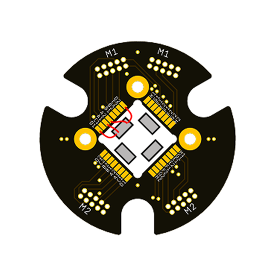
a) Drawing of the carrier PAD32 with four samples, one bonded to the pads.
b) Schematics of the four-point measurement technique.
c) PAD32 sample carrier mounted on a kiutra Puck 36.
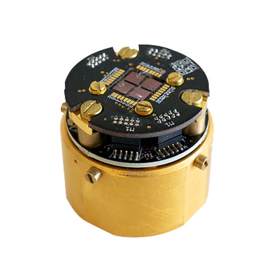
Needle card
As an alternative to wire bonding, we provide a needle card (probe card) solution for contacting samples, enabling non-destructive testing. The sample must be fabricated in a way that its contact pads align precisely with predefined XY positions of the probe card. We offer a small range of probe card layouts for this. Alternatively, we can build custom probe cards for customer-specific layouts. Electrical connections are established via Tungsten-Rhenium needles with flat 60µm tips that press against the sample pads, enabling a stable connection without bonding.
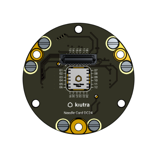
a) Drawing of the needle card.
b) Schematics of the four-point measurement technique.
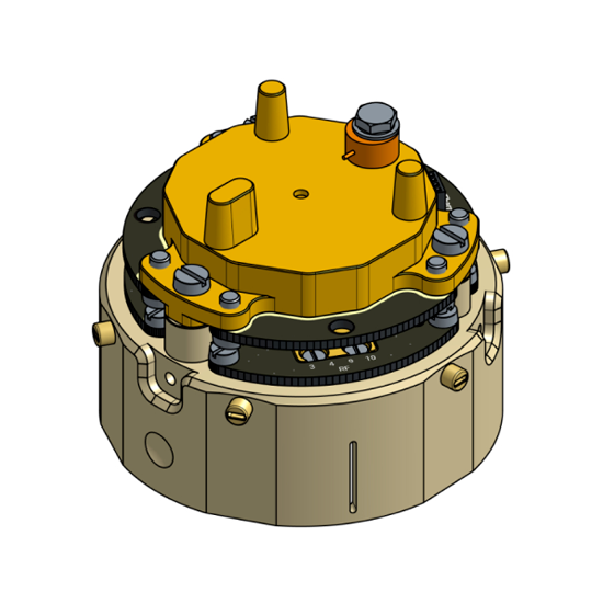
c) Needle card mounted on Puck 55.
Cryostat Interface
The prepared sample carrier is mounted onto a puck and seamlessly connects with the on-puck DC connectors. When loading the puck into an L-Type Rapid cryostat, the DC lines from the puck automatically mate with the internal twisted-pair wiring. At the top plate, the DC lines are divided into two D-Sub 25 connectors. They are connected via two 24-pin, twisted-pair, double-shielded measurement cables to a dedicated transport breakout box.
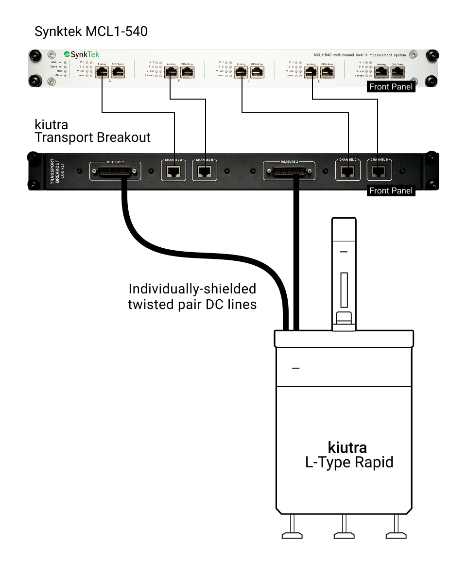
Click image to enlarge.
Measurement setup with a Synktek MCL1-540 lock-in amplifier, a dedicated transport breakout box and an L-Type Rapid cryostat.
Standard measurement protocol
1. The sample puck with the sample carrier and the mounted, wire-bonded device is loaded into the cryostat and cooled down to bath temperature.
2. The puck is further cooled down to the lowest target temperature (50mK or 100 mK).
3. The temperature is ramped from the lowest to the highest target temperature (4K, 20K, or 300K) while voltage and excitation current are continuously measured using a lock-in amplifier. If multiple samples are placed on the sample carrier, the parameters are recorded by using multiple channels of the lock-in amplifier.
4. The sample puck is warmed up to room temperature and unloaded from the cryostat.
A waiting time is included after each cooling step to ensure proper thermalization of all components. The standard measurement procedure can be extended to cover broader temperature ranges (50 mK, 40 K or up to 300 K). Additionally, a room-temperature resistivity measurement of the mounted device can be performed outside the cryostat.
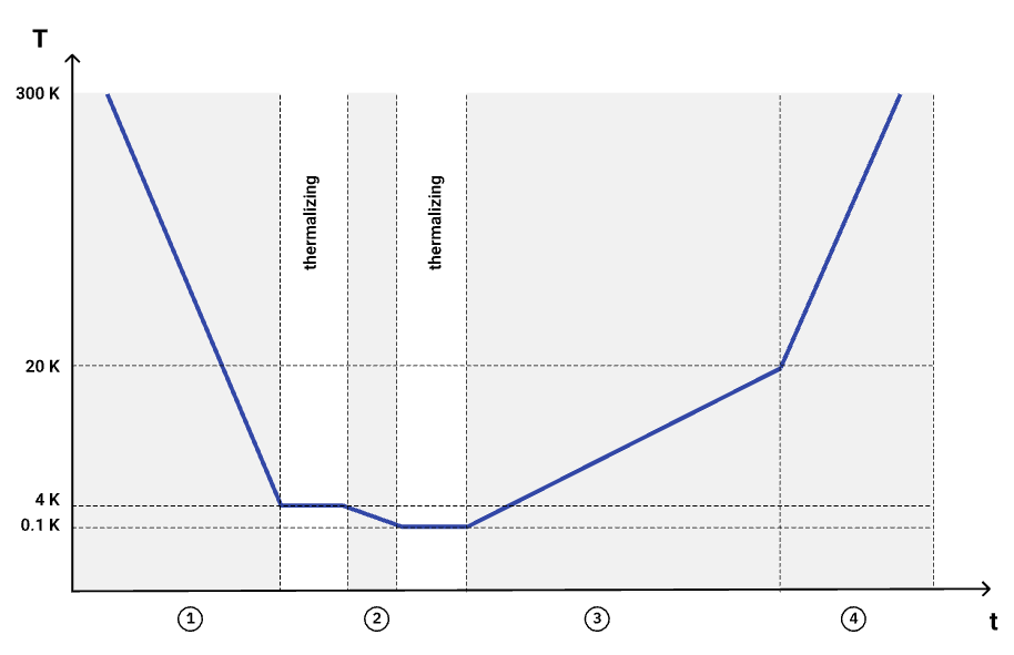
Temperature profile over time during the measurement cycle (dark blue). The curve shows the initial cooldown, waiting periods for thermalization, the temperature ramp up to 20 K (during which the data of interest is recorded), and the final warm-up for puck removal.
The standard measurement configuration uses the following parameters:
*Can be extended (50 mK, 40 K, 300 K)
Can’t find what you need?
We support custom measurement requests for setups outside our standard protocol. Please get in touch for a quote. This will include a one-time setup fee. If you run the same measurement again later, we will reuse the protocol at no extra cost.
Email us at: info@kiutra.com.